Benodigdheden voor communicatie via RS-232.
Communication via RS-232 requires a number of things. Details here.
To the Main index
To the RS-232 index

The tape recorder.
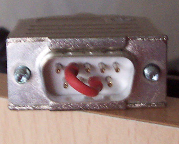
Studer tape recorders models A8nn may be equipped with a 9 pin D-sub (DB-9) connector. Revox models C270, C274 and C278 are equipped with a 7 pin DIN connector. Both can be used to connect the recorder to a computer. Both connector types are still available in electronics stores.
THe Studer recorders need to be equipped with a serial remote controller 1.810.751 This controller, with its DB-9 connector bus, may or may not be there. The controller has a number of jumpers and DIL-switches to watch. These should be set to RS-232 usage with optional settings for baud rate, number of data bits, stopbits and parity. These settings are ususally set to 9600, 8, 1, none respectively, which is good to start with.
The computer.
Any modern computer or laptop will do. It should have a serial RS-232 bus, but nowadays these buses are out of fashion. As an alternative you can use a USB-to-RS232 adapter, since most computers will be equipped with USB-ports. I used a 10-euro LogiLink AU0002B. This adapter is based on a Profilic PL2303-chip that will be recognized by modern operating systems. Windows' device manager will show a serial port COM1 or COM2, running Linux it is named /dev/ttySn.
The cable.
Common serial computer cables, either straight or cross, will not work. That's because
the Studer pin layout deviates from the norm in the computer world. Hence you need
to make a custom cable. You might use an old computer cable for that, but you will
have to solder a new connector to at least one end.
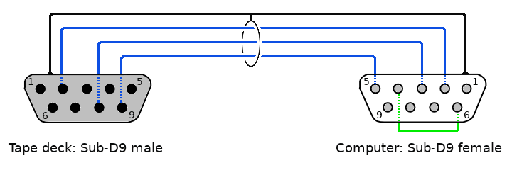
The recorders work with RS-232 without hardware flow control. This means that
basically only 3 wires are needed: TX (transmit data), RX (receive data) and ground.
These are the blue wires in the pictures.
For Studer machines the cable should be like this:
For the Revox models C270, C274 en C278 the cable should be like this:
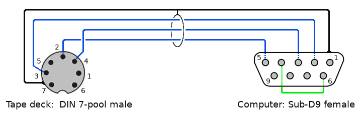
For Revox: Here pins 2 (ground), 3 (tx, transmit data) and 4 (rx, receive data). of the male DIN-plug for the tape deck must be connected to pins 5 (ground), 2 (tx) and 3 (rx) respectively. These are the blue wires in the picture. The metal shielding of the cable, if it is there, can be soldered to the metal casing of the connectors (the black wire in the pictures). It is not necessary for operation, but in case of very long cables (50 feet or more) it is recommended. A warning to C27n owners: Pins 6 and 7 in the DIN-plug carry resp. 24 volts and ground for a remote control. Make sure these pins remain properly isolated.
The blue wires are basically all that is needed for serial communication. However, with a few laptops it would only work when I connected (bridged) pins 4 (DTR) and 6 (DSR). It is the green wire inside the computer connector. Some computers seem to insist on using hardware flow control, even if it is not supported by the counterpart. The tape reocrders don't have pins for DTR and DSR. So depending on your hardware and system software this green wire may be needed as well. Adding it doesn't harm. The tape decks don't do hardware flow control, to the computer the green bridge merely simulates the 'ready' signal from its counterpart.
Some people ask whether we see the front side or the soldering side of the
connectors here. It is the front side, not the soldering side.
It doesn't really matter. Both Sub-D and DIN-connectors will always have
the pin numbers printed on the soldering side, sometimes on both sides.
The pin numbers are always leading.
When everything is there you can start communicating. You will find an introduction
using PuTTY (a well-known, free terminal client) here.